
Daylight Sensor Wiring Diagram
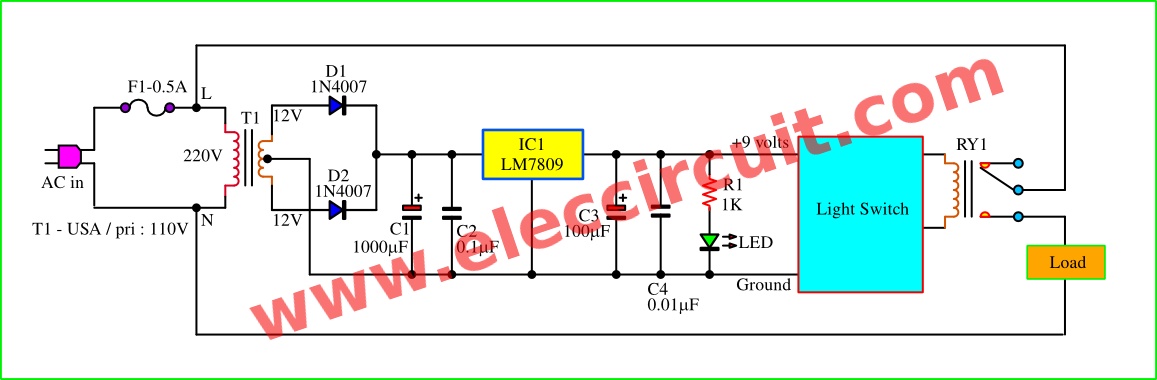
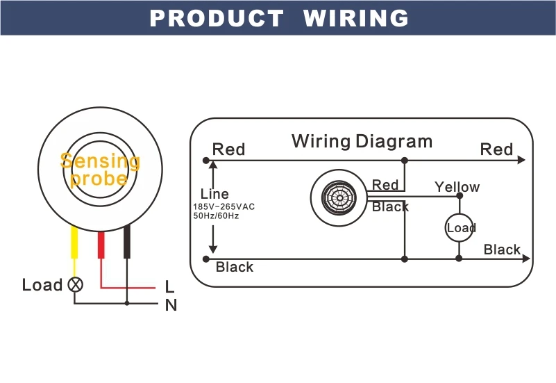
Figure 2 block diagram and 9 volts dc regulation of daylight sensor switch circuit. The sensor red wire will connect to the wire which goes to the light fixture.
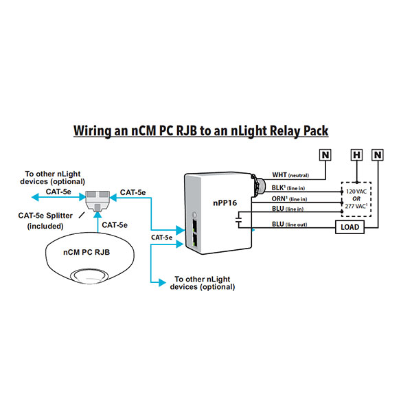
NCM ADCX RJB nLIGHT DAYLIGHT SENSOR PRIMARY & SECONDARY ZONES DIMMING LiteRite Controls

Daylight harvesting standard sensor product line selling sensor switch 2 3 4 6.

Daylight sensor wiring diagram. At times, the wires will cross. Wiring to sensor ease of installation power pack needed investment $ line voltage vac small private office, high bay: Lightleeder evo integrated (wd0614) wiring diagrams.
A device that reads available light and sends a signal to the control system. • the effective window height (h) starts 3 ft (1 m) up from the floor or at the window sill, whichever is higher, and ends at the top of the window. Schematron.org ceiling mount wiring diagram occupancy sensors choosing the correct sequence of operation ceiling occupancy sensor.
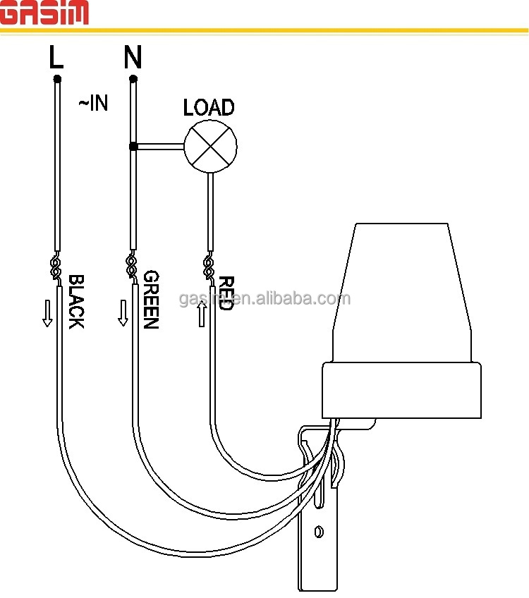
Black wire is 120 volts, so turn off switch or circuit breaker. The actual light, which is situated above it, is cabled separately. Single sensor controls circuit line voltage
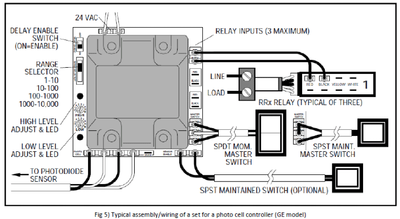
A form of daylighting in which multiple daylight rows are controlled by the same sensor. Ac line, and more) and connecting all wiring as figure 5. Y:tech directoryinstalls, cutsheets,& wiringmaster wiring diagramsnx diagrams_preliminaryroom controller_daylight sensor author:
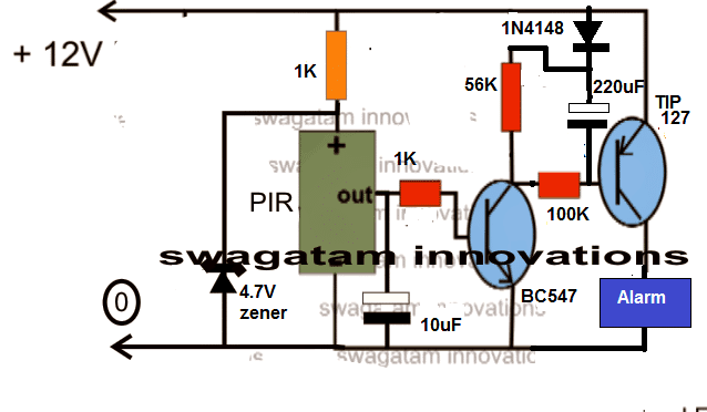
The light sensor circuit is an electronic circuit designed using (light sensor) ldr, darlington pair, relay, diode, and resistors which are connected as shown in the light sensor circuit diagram. Utilizing zones to stagger the dimming and switching of lighting loads. Which is the circuit diagram below:
Sensor switch ® solutions are a leader in lighting control innovation, offering a broad selection of standalone to fully networked controls to meet every application need. Utilizing the ambient (natural & artificial) light present in a space. The hb011 is supplied with two.
The new sensor to be fitted is a titan tp140b/tp140w. The sensor blue wire is not used and should be capped off with a wire nut. A group of fixtures adjusted equally based on daylighting readings daylight sensor:
Determine the proper location of the daylight sensor using the adjacent diagram. Daylight saving light sensor wiring diagram wiring diagram wrg 3991 day night switch wiring diagram bulfyss 230volt auto day night on and off photocell ldr sensor water proof lighting switch multicolour pack of 2 let s learn day night switches by walnut innovations 28 how to wire a day night switch diagram day night 6a wiring diagram wiring. Nlight control system installation worksheet/nlight project installation form/.
Here is my wiring diagram ( third photo) and instructions: In today's post, i'm going to share a simple light activated relay circuit. Lightsync occupancy sensor input module (wd0603) wiring diagrams.
Within a typical nlight network, multiple zones are wired individually to a bridge. P:jimenez a_designhubbnxp 2 functionnxp2 npd drawingsmike cranenxp2_8_daylight sensor layout1 (1) author: Daylight harvesting is an energy management technique that reduces overhead lighting use by:
The actual light is separate and already connected. Connect all 3 white wires (from house, from sensor and from light) together. The sensor green wire will connect to the ground wire in the wallbox.
There'll be primary lines that are represented by l1, l2, l3, and so on. • the arrow on the daylight sensor points toward the area viewed by the sensor. Connect sensor's black wire to black wire coming from house.
Dimming or switching off lighting when sufficient ambient light is present or when the space is unoccupied. Connect red sensor wire to light's black wire. But, it does not imply connection between the cables.
Injunction of two wires is usually indicated by black dot to the intersection of two lines. A potentiometer is employed for end users to set the brightness level, so that the daylight sensor can read, measure the. The sensor black wire will connect to the hot wire in the wallbox.
Then test this project watch in the video below and then installed this project. As stated previous, the lines in a wiring a motion sensor light diagram signifies wires. A 230v ac supply is provided to the load (in this.
Daylight sensor = photo cell = photo sensor multiple row daylighting: • place the daylight sensor so its viewing area is The cdt ceiling mounted low voltage occupancy sensor is a passive infrared ( pir) and ultrasonic wiring diagram 1:
Durable pb switch to lightsync input module (wd0606)
[DS02] Daylight Sensor Hytronik


Lutron Daylight Sensor Wiring Diagram For Your Needs
Daylight Sensor Wiring Diagram 120v

Wiring Diagram Info 25 Daylight Sensor Wiring Diagram
Wiring Diagram Info 25 Daylight Sensor Wiring Diagram

Daylight Sensor Wiring Diagram 120v
Daylight sensor switch circuit,control artificial waterfall
Daylight Sensor Wiring Diagram 120v


Daylight Sensor MS01 Enlarge
How To Make A Daylight Sensor Work
Daylight Light Sensor Adjustable Photocell Switch Buy Photocell Switch,Photocell Light Switch
A BCIT Student Studies The Value Of Daylight Sensors In NE1 Atrium

Daylight Sensor Wiring Diagram 120v
Wiring Diagram Info 25 Daylight Sensor Wiring Diagram
Daylight Sensor Wiring Diagram 120v

[HIR01 + HC038V / HIR01 + HCD038 ] Detached PIR Sensor Daylight Harvest Hytronik


Daylight Sensor Wiring Diagram 120v
Zigbee On/Off Area Controller

Daylight Sensor Wiring Diagram 120v

